- 您现在的位置:买卖IC网 > Sheet目录332 > IRMD2336DJ (International Rectifier)IC MOSFET DRIVER
�� �
�
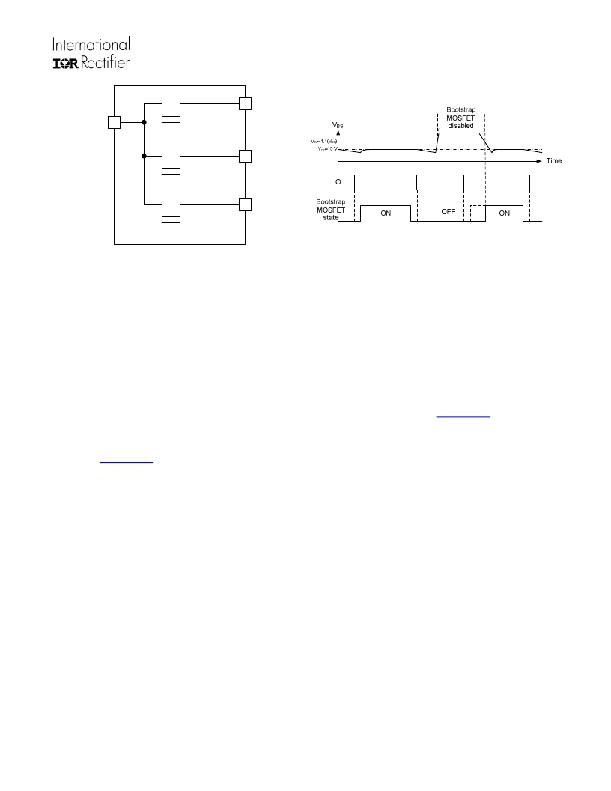
�IRS2336x(D)� Family�
�V� B1�
�V� CC�
�V� B2�
�V� B3�
�Figure� 22:� Internal� bootstrap� MOSFET� connection�
�Figure� 23:� Bootstrap� MOSFET� state� diagram�
�A� bootstrap� MOSFET� is� suitable� for� most� of� the� PWM� modulation� schemes� and� can� be� used� either� in� parallel� with� the�
�external� bootstrap� network� (i.e.,� diode� and� resistor)� or� as� a� replacement� of� it.� The� use� of� the� integrated� bootstrap� as�
�a� replacement� of� the� external� bootstrap� network� may� have� some� limitations.� An� example� of� this� limitation� may� arise�
�when� this� functionality� is� used� in� non-complementary� PWM� schemes� (typically� 6-step� modulations)� and� at� very� high�
�PWM� duty� cycle.� In� these� cases,� superior� performances� can� be� achieved� by� using� an� external� bootstrap� diode� in�
�parallel� with� the� internal� bootstrap� network.�
�Bootstrap� Power� Supply� Design�
�For� information� related� to� the� design� of� the� bootstrap� power� supply� while� using� the� integrated� bootstrap� functionality�
�of� the� IRS2336xD� family,� please� refer� to� Application� Note� 1123� (AN-1123)� entitled� “Bootstrap� Network� Analysis:�
�Focusing� on� the� Integrated� Bootstrap� Functionality.”� This� application� note� is� available� at� www.irf.com� .�
�For� information� related� to� the� design� of� a� standard� bootstrap� power� supply� (i.e.,� using� an� external� discrete� diode)�
�please� refer� to� Design� Tip� 04-4� (DT04-4)� entitled� “Using� Monolithic� High� Voltage� Gate� Drivers.”� This� design� tip� is�
�available� at� www.irf.com� .�
�Separate� Logic� and� Power� Grounds�
�The� IRS2336xD� has� separate� logic� and� power� ground� pin� (V� SS� and� COM� respectively)� to� eliminate� some� of� the� noise�
�problems� that� can� occur� in� power� conversion� applications.� Current� sensing� shunts� are� commonly� used� in� many�
�applications� for� power� inverter� protection� (i.e.,� over-current� protection),� and� in� the� case� of� motor� drive� applications,� for�
�motor� current� measurements.� In� these� situations,� it� is� often� beneficial� to� separate� the� logic� and� power� grounds.�
�Figure� 24� shows� a� HVIC� with� separate� V� SS� and� COM� pins� and� how� these� two� grounds� are� used� in� the� system.� The�
�V� SS� is� used� as� the� reference� point� for� the� logic� and� over-current� circuitry;� V� X� in� the� figure� is� the� voltage� between� the�
�ITRIP� pin� and� the� V� SS� pin.� Alternatively,� the� COM� pin� is� the� reference� point� for� the� low-side� gate� drive� circuitry.� The�
�output� voltage� used� to� drive� the� low-side� gate� is� V� LO� -COM;� the� gate-emitter� voltage� (V� GE� )� of� the� low-side� switch� is� the�
�output� voltage� of� the� driver� minus� the� drop� across� R� G,LO� .�
�www.irf.com�
�29�
�?� 2009� International� Rectifier�
�发布紧急采购,3分钟左右您将得到回复。
相关PDF资料
IRPLLED1A
IC MOSFET DRIVER
IRPLLED7
IC MOSFET DRIVER
IRPP3637-06A
BOARD REF DESIGN POWIR+
IRS2001MPBF
IC DRIVER HIGH/LOW SIDE 16MLPQ
IRS2001SPBF
IC DRIVER HI/LO SIDE 200V 8-SOIC
IRS2003STRPBF
IC DRIVER HALF-BRIDGE 8-SOIC
IRS2004PBF
IC DRIVER HALF-BRIDGE 8-DIP
IRS2011PBF
IC DRIVER HI/LO SIDE 8-PDIP
相关代理商/技术参数
IRMD26310DJ
功能描述:电源管理IC开发工具 COMPLETE 3-PHASE AC IRS26310DJ REF Kit RoHS:否 制造商:Maxim Integrated 产品:Evaluation Kits 类型:Battery Management 工具用于评估:MAX17710GB 输入电压: 输出电压:1.8 V
IRMDAC2
制造商:IRF 制造商全称:International Rectifier 功能描述:IR2133 Reference Design Kit: 3-Phase 230VAC 3HP Motor Drive 3-Phase 230VAC 3HP Motor Drive
IRMDAC3
制造商:IRF 制造商全称:International Rectifier 功能描述:Reference Design Kit: 3-Phase 460VAC 3HP Motor Drive
IRMDSS1
功能描述:KIT DESIGN IC REF SOFT START RoHS:否 类别:编程器,开发系统 >> 过时/停产零件编号 系列:- 标准包装:1 系列:- 类型:MCU 适用于相关产品:Freescale MC68HC908LJ/LK(80-QFP ZIF 插口) 所含物品:面板、缆线、软件、数据表和用户手册 其它名称:520-1035
IRMFB-EK
功能描述:光学传感器开发工具 Si1140 Multifunction Demo Board
RoHS:否 制造商:ams 工具用于评估: 接口类型: 最大工作温度:
IRM-H136/TR2
制造商:EVERLIGHT 制造商全称:Everlight Electronics Co., Ltd 功能描述:Infrared Remote-control Receiver Module
IRM-H136-TR2
制造商:EVERLIGHT 制造商全称:Everlight Electronics Co., Ltd 功能描述:Infrared Remote-control Receiver Module
IRM-H138/TR2
功能描述:红外接收机 Infrared Remote RoHS:否 制造商:Vishay Semiconductors 载频:20 kHz to 60 kHz 传输距离:5 m 显示角:+/- 50 deg 高电平脉冲宽度: 低电平脉冲宽度: 最小高电平输出电压: 输出电流:5 mA 工作电压:2.5 V to 5.5 V 电源电流:0.9 mA 功率耗散: 最大工作温度:+ 85 C 最小工作温度:- 25 C 封装 / 箱体: 封装:Reel